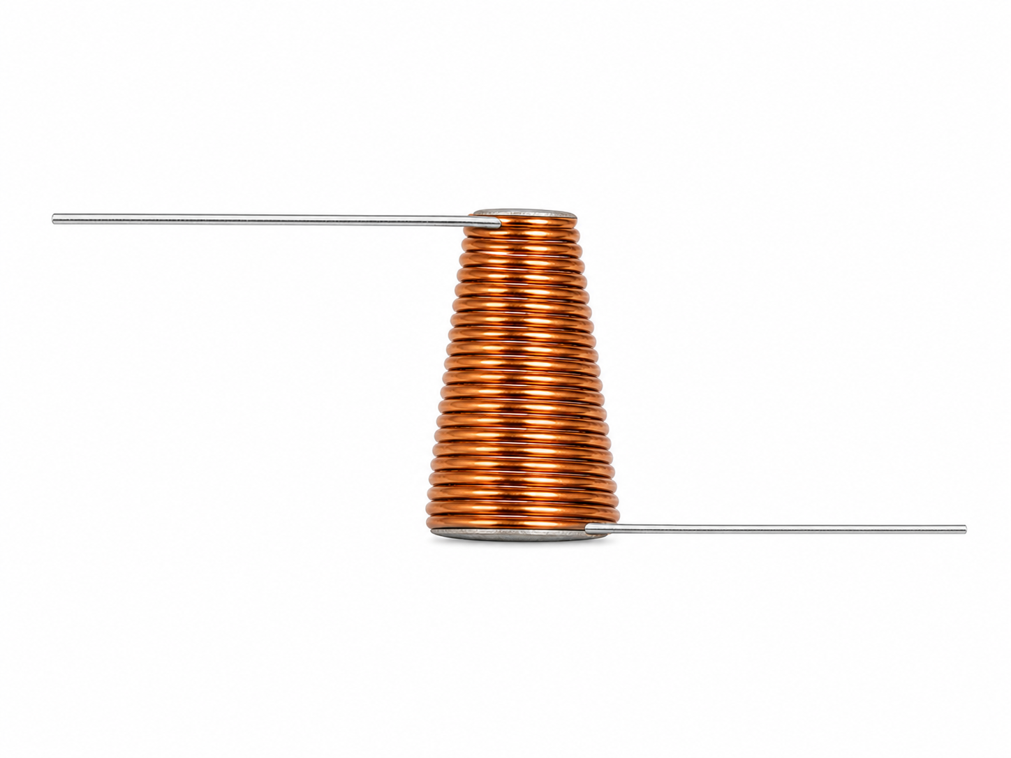
WIDEBAND RF CHOKE
Conical
Inductor
- — 80—600 nH
- — 200—800 mA
- — Up to 40 GHz
MICROWAVE COMPONENTS · 91M
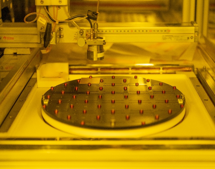
Focused on the development and production of conical inductors and single-layer ceramic chip capacitors. Built for RF, microwave, and millimeter-wave engineers with clear specs, verifiable data, and assisted part selection.
Bias Network
•RF Choke
•Coupling / DC Block
•Decoupling / Filtering
•Power Amplifier
PRODUCT FAMILIES
Model, dimensions, electrical data, and recommended applications are placed directly in the page body so engineers and AI can read, compare, and cite them accurately.
PARAMETRIC SELECTOR
Quickly pre-screen existing products by operating frequency, current, and application. Results come from real page data and do not replace final simulation or lab validation.
Every result keeps its parameter basis for future integration with a conversational AI selector.
AJAX
Filtering is based on recommended frequency, current rating, application, and voltage in the current product series. Final selection should still be verified in the actual circuit.
ENGINEERING DATA
The following parameters are entered from current product documents. Before formal release, it is recommended to add datasheets, test conditions, S-parameters, and revision dates.
WIDEBAND RF CHOKE
| Model | Inductance | Length L | Current Rating | Recommended Frequency |
|---|---|---|---|---|
| 91MLT1500503R | 80 nH ±20% | 0.75 mm | 200 mA | 300 MHz–40 GHz |
| 91MLT2000503R | 140 nH ±20% | 1.0 mm | 200 mA | 200 MHz–40 GHz |
| 91MLT2000803R | 160 nH ±20% | 1.6 mm | 500 mA | 200 MHz–30 GHz |
| 91MLT2001503R | 160 nH ±20% | 3.0 mm | 800 mA | 200 MHz–20 GHz |
| 91MLT2500503R | 240 nH ±20% | 1.25 mm | 200 mA | 100 MHz–40 GHz |
| 91MLT2500803R | 260 nH ±20% | 2.0 mm | 500 mA | 100 MHz–30 GHz |
| 91MLT4000503R | 600 nH ±20% | 2.0 mm | 200 mA | 10 MHz–40 GHz |
SINGLE LAYER CERAMIC
| Model | Capacitance | Package Size | Voltage Rating | Termination | Recommended Use / Frequency |
|---|---|---|---|---|---|
| 91MCC100G | 10 pF ±20% | 0.25 × 0.25 × 0.12 mm | 100 V | Single Side | Coupling (DC Block) / 4–40 GHz |
| 91MCC220G | 22 pF ±20% | 0.38 × 0.38 × 0.15 mm | 50 V | Single Side | Coupling (DC Block) / 2–40 GHz |
| 91MCC101D | 100 pF ±20% | 0.76 × 0.76 × 0.20 mm | 100 V | Double Side | Decoupling (Filtering) / DC |
| 91MCC101G | 100 pF ±20% | 0.38 × 0.38 × 0.15 mm | 50 V | Single Side | Coupling (DC Block) / 0.4–40 GHz |
| 91MCC331G | 330 pF ±20% | 0.38 × 0.38 × 0.15 mm | 16 V | Single Side | Coupling (DC Block) / 0.1–40 GHz |
| 91MCC102A | 1000 pF ±20% | 0.76 × 0.76 × 0.15 mm | 50 V | Double Side | Decoupling (Filtering) / DC |
R&D · Production · Test
ABOUT 91M MICROWAVE
91M Microwave focuses on the development and production of passive microwave components, using engineering data as a common language for RF, microwave, and millimeter-wave applications.
ENGINEER FAQ
They are mainly used in broadband bias networks and RF choke applications. The current series covers recommended operating frequencies from 10 MHz to 40 GHz, depending on the model.
First confirm the bias current and operating band, then choose models whose rated current is not lower than your requirement. The current series offers 200 mA, 500 mA, and 800 mA options.
Single-side termination series are suitable for high-frequency coupling and DC blocking, while double-side series are used for decoupling and filtering. Capacitance, voltage rating, package size, and the actual mounting structure should also be checked.
No. The web result is only for preliminary parameter screening. Before mass production, simulation and real-world validation are still required with the actual circuit, mounting parasitics, temperature, and power conditions.
TALK TO AN ENGINEER
Business email: 501728034@qq.com | Phone: +86 18602806932